Category
Cut Type Knurling
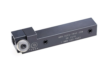
Cut Type Knurl Holders
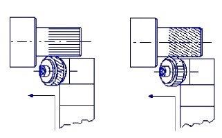
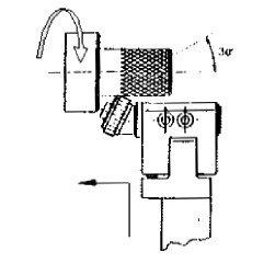
CUT TYPE Knurling is not widely used in U.S. market, but common in the rest of the world. The knurling dies are skewed (layed over 30°) to the work piece axis creating a cutting action rather than a forming process. Often times when knurling non-ferrous material (aluminum, brass, etc.) the forming action work hardens the material causing the crest to become brittle and break off. Not so with the cut type knurl - the milling action leaves a sharp solid crest for a perfect knurl.
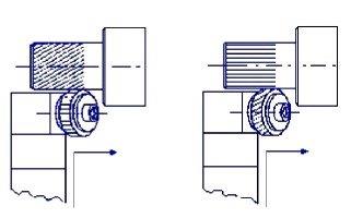
There are both single and two die holders available. Interesting is the fact that to get the diamond pattern two straight tooth dies are used (on a two die holder) and for a straight pattern a single helical die is used. It is believed that the diameter of a finished knurled part can be more easily controlled with this method; just remember you aren't increasing the diameter of the work piece. Holder shanks can be mounted at right angle to the piece and always use plenty of coolant to wash away chips.
It's best to experiment with the Speeds & Feeds to get the best looking knurl, but generally a feed in the range of 0.07-0.2 mm/rev and a surface speed of 15-55 m/min will work. With softer metals (aluminum & brass) stay on the high end, but with stainless and other high alloys use the lower end. For stainless steel, or other higher alloyed steels, you should expect lower wheel life than that obtained with "forming" wheels
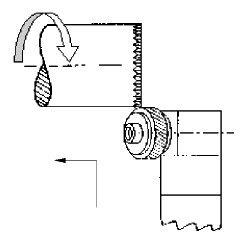
With a fairly rapid infeed to the final minor diameter of the workpiece, cut type knurls will normally track on any diameter. If not, a small variation to the infeed rate, or blank diameter will normally correct any problem. Once established, the blank diameter should be held within +/- .025mm (.001"). Depth of the cut should be .5-.6mm x pitch. The method of approach is very important to getting a good looking knurl. On the end of the work piece, approximately 1-2 pitches wide, plunge the tool straight into the part. After reaching the correct depth then traverse across the part. Note: Do not just feed axially.
Single Knurl Holders | ||
|---|---|---|
|
Inch and Metric Dimensions |
 |
|
|
These knurling tools will produce a straight knurl using a 30° RH diagonal knurling die or a 30° RH diagonal knurl with a straight knurling die. The knurl depth should be approximately 50% of the knurl pitch. Surface speed is in the range of 50-200 ft/min (depending upon material) with a feed rate of around .005"/Rev. If the knurl is not parallel, adjust the head. Be sure to use plenty of coolant to flush away the chips. *Each time the wheels are changed, a high pressure graphite based lubricant should be applied to the bore andbushing to reduce the likelihood of the wheel seizing on the bushing. |
||
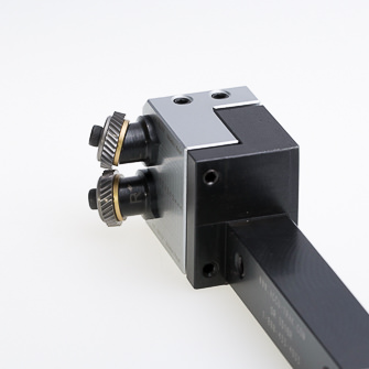
Double Knurl Holders | ||
|---|---|---|
|
Inch Dimensions |
 |
|
|
These knurling tools will produce a 30° diamond pattern using two straight knurling dies. Set the work diameter on the tool scale by unlocking the socket head screws from the rear and tapping to break the lock. The tool has to be mounted in the machine on center. Use the fine adjustment screws to insure both knurls are hitting equally. The depth of cut should be approximately 50% of the knurl pitch and feed at around .005"/Rev. Surface speed should be in the range of 50-200 ft/min depending on material. Always have plenty of coolant flushing the work area. *Each time the wheels are changed, a high pressure graphite based lubricant should be applied to the bore andbushing to reduce the likelihood of the wheel seizing on the bushing. |
||
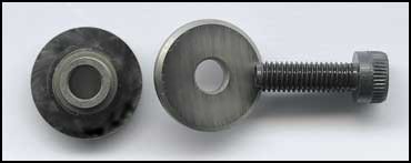
Replacement Parts for Cut Type Holders | ||
|---|---|---|
|
|
|
 |
|
SINGLE KNURL CUT TYPE HOLDERS
|
|||
 |
 |
||
|
Straight knurling RAA
Right-hand knurl BR 30 |
Right-spiral RBR 30°
Straight knurl AA |
Left-spiral RBL 30°
Straight knurl AA |
Straight knurling RAA
Left-hand knurl BL 30° |
|
|
|
 |
|
|
|
|
|
|
|
|
|
 |
|
|
|
|
|
DOUBLE KNURL CUT TYPE HOLDERS
|
|
 |
 |
|
Diamond knurl RGE 30°
Upper axle straight knurl AA Lower axle straight knurl AA |
Cross knurl RGE 45°
Upper axle left hand knurl BL15° Lower axle right hand knurl BR15° |
|
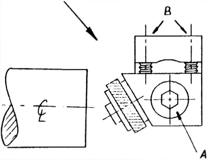
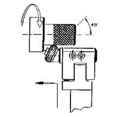
First, decide if you require a 30º "diamond" knurl or a 45º "cross" knurl on your component. The knurls should be fitted to the holder as shown using a high temperature grease for initial lubrication. Tighten the socket cap screw to ensure the knurls are secured adequately and that they are free to rotate. |
||
|
|
 |
|
|
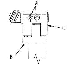
Loosen the two set screws (B) which prevent the head from pivoting slightly. Loosen the main head pivot screw (C) just enough to allow the head to centralize when it touches on the component. |
||
|
|
||
|
|
||
|
|
 |
|
|
|
||
|
|
||
|
|
||
Speeds and Feeds for Cut Knurling
| Material | Knurl Dia. (mm) |
Workpiece Dia. 2-12mm, .079"-.472" |
Workpiece Dia. 13-40mm, .512"-1.575" |
Workpiece Dia. 41-250mm, 1.614"-9.843" |
|||
| Speed (SFM) | Feed (in/rev) | Speed (SFM) | Feed (in/rev) | Speed (SFM) | Feed (in/rev) | ||
| Mild Steel |
8.9 | 115 | .002-.003 | - | - | - | - |
| 14.5/15 | 148 | .003-.004 | 131 | .003-.004 | - | - | |
| 21.5/25 | 197 | .003-.006 | 197 | .003-.006 | 164 | .003-.006 | |
| Tool Steel |
8.9 | 82 | .002-.003 | - | - | - | - |
| 14.5/15 | 115 | .002-.003 | 98 | .002-.003 | - | - | |
| 21.5/25 | 164 | .002-.005 | 148 | .002-.005 | 131 | .002-.005 | |
| Stainless Steel |
8.9 | 72 | 0.002 | - | - | - | - |
| 14.5/15 | 98 | .002-.003 | 92 | .002-.003 | - | - | |
| 21.5/25 | 131 | .002-.005 | 115 | .002-.005 | 105 | .002-.005 | |
| Brass | 8.9 | 197 | .002-.004 | - | - | - | - |
| 14.5/15 | 230 | .003-.008 | 197 | .003-.005 | - | - | |
| 21.5/25 | 295 | .003-.008 | 295 | .003-.008 | 262 | .003-.008 | |
| Bronze | 8.9 | 115 | .002-.003 | - | - | - | - |
| 14.5/15 | 148 | .003-.004 | 131 | .003-.004 | - | - | |
| 21.5/25 | 197 | .003-.006 | 197 | .003-.006 | 180 | .003-.006 | |
| Aluminum | 8.9 | 197 | .002-.005 | - | - | - | - |
| 14.5/15 | 230 | .003-.007 | 230 | .003-.007 | - | - | |
| 21.5/25 | 295 | .004-.010 | 262 | .004-.010 | 230 | .004-.010 | |
| Cast Iron | 8.9 | 82 | .002-.003 | - | - | - | - |
| 14.5/15 | 115 | .002-.003 | 98 | .002-.003 | - | - | |
| 21.5/25 | 164 | .002-.005 | 148 | .002-.005 | 131 | .002-.005 | |
