3 Die End Rolling Holders
Heavy Duty Compact Three Die External Knurling Holder | ||
|---|---|---|
|
Inch and Metric Dimensions |
 |
|
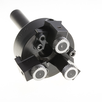
| Compact design makes it ideal for use on screw machines and CNC lathes when axial feed knurling from the turret. Parts are self supported and they can extend thru the shank for long jobs. We recommend using "CONVEX"Knurls Holder can also be adapted for burnishing and internal knurling. To Set Up: Determine Blank Diameter using Table I. Subtract the approximate knurl depth to obtain the minor diameter of the part. IN THE MACHINE set the three carrier blocks to this size or a few thousandths larger and test roll some parts. For further small adjustments move only one of the blocks. NOTE: Adjustments are made from the front of the holder. Recommended feed rate is .010 - .030" per rev. (off twice as fast) with a spindle speed of approximately 50 - 150 SFPM. |
||
Compact Self-Centering Three Die Holder with Synchronized Adjustment | ||
|---|---|---|
|
Inch and Metric Dimensions |
 |
|
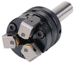
| Knurl head for knurling small diameter components. Fitted with three jaws arranged at 120º which can be adjusted simultaneously by means of a synchronizing ring. This tool has a built-in mechanism that compensates any misalignment between the chuck and turret centerlines. Recommended for use on CNC, automatic, multi-spindle lathes and others. | ||
Cam Adjustable Internally Synchronized Three Die Spline Rolling Heads | ||
|---|---|---|
|
CUSTOM CONFIGURATIONS |
|
 |
|
Synchronized spline rolling heads are used to roll precision parts which must fit with a mating part. They are also used where the length of the part would cause excessive deflection when rolling from one side. A synchronizing mechanism is needed when more than one straight die is used to prevent mis-tracking and minimize spacing error. Mis-tracking is when rolling dies produce the wrong number of teeth (often twice as many as desired). Spacing error is when the distance from tooth to tooth varies, causing mating parts not to fit together. The synchronizing gear aligns the teeth on each rolling die in relation to the others. When rolling the synchronizing gear is pushed back into the head. When the part is retracted, a spring returns the synchronizing gear to its original position. The cam adjustable type allows the three dies to be adjusted with a single adjustment, making setup easier than heads with independent adjustment. |
||
Replacement Parts
|
HOLDER
|
**CARRIER BLOCKS
with pins |
**BINDERS
|
**ADJ. SCREWS
|
**PINS
|
||||
|
TOOL#
|
PRICE
|
TOOL#
|
PRICE
|
TOOL#
|
PRICE
|
TOOL#
|
PRICE
|
|
|
OR 3DBP_
|
$72 ea.
|
$36 ea.
|
$13.00 ea.
|
$11.30 ea.
|
||||
|
OR 3DEP_
|
$72 ea.
|
$36 ea.
|
$13.00 ea.
|
$11.30 ea.
|
||||
|
OR 3DGK_
|
$72 ea.
|
$36 ea.
|
$13.00 ea.
|
$11.30 ea.
|
||||
|
OR 3DGK_
|
$143 ea. |
$36 ea.
|
$13.00 ea.
|
$11.30 ea.
|
||||
|
OR 3DGK_
|
$154 ea. |
$36 ea.
|
$13.00 ea.
|
$16.70 ea.
|
||||
|
OR 3DML_
|
$119 ea.
|
$36 ea.
|
$13.00 ea.
|
$31.90 ea.
|
||||
OPERATING INSTRUCTIONS FOR 3 DIE SELF CENTERING HOLDERS
1. Tool Adjustment
The tool has a floating handle for adjustment of the position of the knurls to enable them to operate in perfect alignment with the part. Secure the tool to the center sleeve on the tailstock or to the turret of the automatic lathe facility, and check that it is aligned with the part to be processed. The part to be machined must rotate concentrically to prevent abrupt entry of the tool during knurling. It is advisable to carry out surfacing on the part prior to knurling.
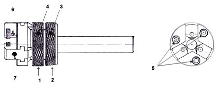
Release screw no. 5 locking out the knurl holder claws. Release screws no. 3 and 4 which are locked out by nuts no. 1 and 2.
Rotate nut no. 2 securing the handle and the head of the knurler unit in such a way that this moves around unobstructed. Rotate nut no. 1 and open the knurl-holder arms to a diameter slightly greater than that of the part to be knurled. Move the turret or the tailstock (depending on the lathe being used) until the knurls are positioned at the start of the distance to be knurled, so that the knurls may later be removed from the contact area. Rotate the chuck manually and act on nut no. 1, closing up the claws until the knurls make contact with the part, and then on nut no. 2 to lock out the knurling unit and align it with the handle.
2. Starting the knurling process
Without removing the tool from the part, rotate nut no. 2 so that the knurls start to deform the part, creating grooves with a sharp crest edge. Each turn of nut no. 2 moves the knurls through a radius of 1 mm. When the knurl makes contact with the surface of the part, the approximate depth must be 50% of the pitch of the knurl used. For example, if a 2 mm. knurl is to be carried out, depth must be approximately 1 mm. (half a turn of the nut).
Once the required mark has been obtained, lock out screw no. 4 preventing rotation of the nut, and screw no. 5 locking out the knurl-holder claws, leaving the knurler unit ready for operation, and apply the axial movements recommended in the tables.
To remove chips, ease the cutting process, cool the operation and lubricate the knurls, this must be carried out using a considerable flow of coolant, taladrine or cutting fluid.
3. Changing the knurls
To change the knurls, loosen the no. 6 fastening for the knurl shaft, and activate the no. 7 auxiliary outgoing stud on the knurler claw. The stud and the knurl shaft have a conical tip. When the no. 7 stud is moved, the conical tips make contact and the knurl shaft is released from its housing.
Once the knurl has been changed, reposition the shaft in its housing at the level of the knurl-holder claw, and lock it out with the no. 6 fastening. Prior to this operation, the no. 7 auxiliary outgoing stud must be released to prevent any interference.
The tool is supplied without knurls, a set of Allen keys and the no. 7 auxiliary outgoing stud.
4. Troubleshooting
The knurls break easily:
- Excessive knurling depth. Refer back to 2 and make necessary adjustments.
Excessive knurl wear:
- Operating conditions are not correct. Check cutting speed and axial movements.
|
APPROXIMATE INCREASE IN KNURLED DIAMETERS
Using ACCU TRAK Circular or Diametral Pitch Knurls |
||||||
|
TPI
|
Pitch
mm |
Tooth
Angle |
Straight
In. / mm |
Diagonal
In. / mm |
Diamond (ON PART)
|
|
|
Male
|
Female
|
|||||
|
12
|
2.12
|
90°
|
.034" / .86mm
|
.034" / .86mm
|
.038" / .97mm
|
.023" / .58mm
|
|
16
|
1.59
|
90°
|
.025" / .64mm
|
.025" / .64mm
|
.029" / .74mm
|
.017" /.43mm
|
|
20
|
1.22
|
90°
|
.020" / .51mm
|
.020" / .51mm
|
.023" / .58mm
|
.014" / .36mm
|
|
25
|
1.02
|
90°
|
.016" / .41mm
|
.016" / .41mm
|
.018" / .46mm
|
.011" / .28mm
|
|
30
|
0.85
|
90°
|
.013" / .33mm
|
.013" / .33mm
|
.015" / .38mm
|
.009" / .23mm
|
|
35
|
0.73
|
90°
|
.011" / .28mm
|
.011" / .28mm
|
.013" / .33mm
|
.007" / .18mm
|
|
40
|
0.64
|
90°
|
.009" / .23mm
|
.009" / .23mm
|
.010" / .25mm
|
.006" / .15mm
|
|
-
|
||||||
|
35
|
0.73
|
70°
|
.014" / .36mm
|
.014" / .36mm
|
.016" / .36mm
|
.009" / .23mm
|
|
40
|
0.64
|
70°
|
.012" / .34mm
|
.012" / .34mm
|
.013" / .33mm
|
.008" / .20mm
|
|
50
|
0.51
|
70°
|
.009" / .23mm
|
.009" / .23mm
|
.010" / .25mm
|
.006" / .15mm
|
|
60
|
0.42
|
70°
|
.007" / .18mm
|
.007" / .18mm
|
.008" / .20mm
|
.005" / .11mm
|
|
70
|
0.36
|
70°
|
.006" / .15mm
|
.006" / .15mm
|
.007" / .17mm
|
.004" / .10mm
|
|
80
|
0.32
|
70°
|
.005" / .13mm
|
.005" / .13mm
|
.006" / .15mm
|
.004" / .10mm
|
|
-
|
||||||
|
DP
|
Pitch
mm |
Tooth
Angle |
Straight
In. / mm |
Diagonal
In. / mm |
Diamond (ON PART)
|
|
|
Male
|
Female
|
|||||
|
64
|
1.25
|
80°
|
.024" / .61mm
|
.021" / .53mm
|
.024" / .61mm
|
.015" / .38mm
|
|
96
|
0.83
|
80°
|
.016" / .41mm
|
.014" / .36mm
|
.016" / .41mm
|
.010" / .25mm
|
|
128
|
0.62
|
80°
|
.012" / .30mm
|
.010" / .25mm
|
.012" / .30mm
|
.007" / .18mm
|
|
160
|
0.50
|
80°
|
.009" / .23mm
|
.008" / .20mm
|
.009" / .23mm
|
.005" / .13mm
|
