Conical Knurling
|
Often, parts may require knurling on conical or radial surfaces, either for function or decorative purposes. With proper tools and application, a clean, well-formed knurl or serration can be produced.
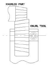
One of the most frequent mistakes when knurling a conical surface is having the knurling tool and the part set with parallel axes. This is shown in figure 1 and is similar to running a pair of bevel gears the wrong way. It can work for larger parts with small conical angles, but as the conical angle increases, the results become worse. This method should only be used when the pitch change from the small to large end of the part is less than 10%.
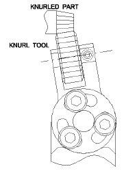
While technically not correct, using a conventional forming knurl inch or forming knurl metric as shown in figure 2 can be effective when rolling on relatively larger diameters with smaller conical angles. The advantage here is that tooling is substantially cheaper, but once again as the conical angle increases the knurled part will be of lesser quality. This method can be used to produce acceptable parts when the pitch change is as high as 15-20%.
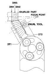
A better method of producing a clean knurl on a conical surface with maximum tool life is shown in figure 3. By using an adjustable angle holder along with the proper conical knurl die, this method makes it possible to roll tapered serrations with a controlled number of teeth and consistent repeatability.
For proper tracking at both ends of the piece, it is necessary to establish the geometrical relationship between the part and the tool with consideration given to the space available for tooling. It is sometimes advantageous to use a shank-type knurling tool where clearance is not available for the conventional style knurl holder.
In certain cases, parts may be knurled with radial teeth on the end of parts, by using a conical knurl of the proper design. Here again, the results depend primarily on establishing the geometric relationship between the part and the tool. For more information on either of the above cases see face knurling.
Whenever knurling on conical and end surfaces, a tracking correction factor is usually applied to the calculated diameter because of many of the many variables involved, such as hardness of material, elasticity of machine tools and tool holders, etc. This factor is necessarily empirical.
For help in selecting the proper tool for your job call Accu Trak at (800) 433-4933 or send us an email with your part requirements.
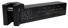
Taper Knurling Holders | ||
|---|---|---|
|
ADJUSTABLE HOLDERS TO ACCOMODATE ANY ANGLE (FOR KNURLING ON CONICAL DIAMETERS) |
Inch Dimensions |
 |
| For Narrow Knurl Bands or small taper angles, KP Series & PH Series Knurls can be used. When the Pitch change is greater than 20% special Conical dies are recommended (see below). |
||
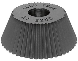
Conical Knurling Dies | ||
|---|---|---|
|
These conical knurling wheels, designed to fit our TAPER KNURLING HOLDERS shown above, are suitable for knurling many straight tooth pattern conical parts including windshield wiper shafts per German knurl spec DIN 72 783. |
Inch Dimensions |
 |
|
When using a single conical knurling wheel from the cross-slide (coming in on the "X" axis), the axial ("Z") position is very important. The pitch of a conical knurl varies from the large end to the small end. Therefore, if the knurl is moved axially, the pitch at the point of contact to the work piece changes which may result in a different number of teeth rolled on the part. If mis-tracking should occur, when first setting up, it can easily be solved by moving the holder a small amount in either direction along the "Z" axis. The usual infeed rate would be .002-.004"/rev. (0.05-0.10mm/rev). Remember that (except for very narrow or low angle conical knurl patterns) the large end of the wheel must contact the large end of the work piece to achieve a clean knurl pattern. This requires a special holder that can present the wheel at the proper angle. An adjustable holder is preferred so that variations in the knurls and/or blanks can easily be allowed for. Please call for help in selecting the proper wheel/holder for your job. Engineering & design charges may apply for some special applications. |
||
Angular Bump Holders | ||
|---|---|---|
|
For Conical Knurling |
Inch Dimensions |
 |
